
Terrestrial communications

From the US to Europe and Asia-Pacific.

Explore real-world submarine fiber maps, then test campus and enterprise connections in the rotating network globe. Start with the existing ocean crossings and build the complete land-to-ocean service path.

REAL-WORLD INFRASTRUCTURE

Under the oceans.
Between your markets.

See the submarine fiber systems that connect land networks across the Atlantic, Pacific and beyond. Begin with cables listed as in service, then inspect a named system and its coastal landings.
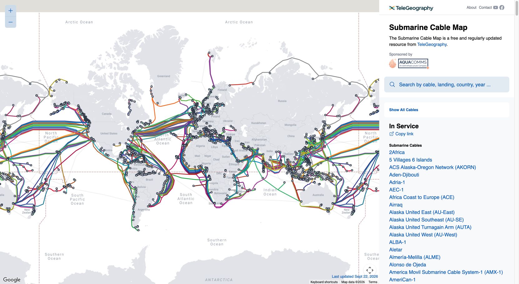
TeleGeography map filtered to in-service submarine cables, showing global ocean crossings and landing points.
Map screen captures © TeleGeography, reproduced unchanged under CC BY-SA 4.0. Captured September 28, 2026; source map updated September 22, 2026. Map-provider credits remain in each image. These are static reference views; open the source for its latest interactive map.

The fiber already connecting continents.

A worldwide view filtered to cable systems listed as in service by TeleGeography. Open the interactive source to search systems, countries and landing points.

Open interactive source map ↗

Mapped cable paths are stylized, not exact seabed coordinates. “In service” is the source’s system classification, not a live outage or availability measurement. Youniverse1 does not claim ownership of these third-party cables.

GLOBAL CABLE CATALOG

TeleGeography

Search cable names, landing points and service status. Inspect existing systems before scoping continental connectivity.

Explore in-service cables ↗

LAND + OCEAN NETWORKS

ITU broadband maps

Compare terrestrial fiber and submarine cable layers. Check each layer’s date and source when reviewing a regional network.

Open the ITU map ↗

Bring the map into your solution: coastal landing → terrestrial backhaul → enterprise gateway → campus. Test capacity, independent paths, recovery and growth in the pilot below.

Continue to the rotating globe & pilot ↓

YOUR TEST ENVIRONMENT

Choose a pilot. Run the starting package.

Reference inputs are provided for every pilot. Change the scale or test condition, then compare the current configuration with growth. No technical file is needed.

Loading pilot controls…

NETWORK IN MOTION

Your network. From orbit to Earth.

Illustrative test environment

Explore satellites, reference ground gateways and the campus service path. The figures below use your selected pilot inputs. Constellation layouts and moving links illustrate the architecture; they do not predict orbital contacts.

Drag to explore the constellation · select a spacecraft or ground endpoint

Visible layers
54 reference ground gateways

United States 15 · Canada / Mexico 3 · Europe 8 · Asia 12 · Africa 6 · South America 6 · Oceania 4

Illustrative regional planning locations. Select a gateway to center the globe and inspect its role. Pilot gateway capacity is configured separately.

Connected pilot devices—
Primary utilization—
Window delivery—
Gateway utilization—
Inspect a network role

Earth & constellation

Drag the globe or use arrow keys to change the view. Select a satellite or ground endpoint to inspect its role.

Current configuration

Loading selected pilot preview…

Cyan: satellite and ground architecture. Green in the globe view: reference ground path. Amber: alternate path or capacity review. Red: interrupted campus primary path.

Constellation growth is a view option; orbit bands and motion are illustrative, not to physical scale. Connected-device counts and capacity figures come from the pilot. Cable corridors illustrate transatlantic, transpacific and Asia-Pacific connections, not exact cable routes. This is a local visualization, with no live spacecraft telemetry or device control.

Cinematic scene and spacecraft: original concept artwork. Globe Earth texture: NASA Blue Marble / Earth Observatory.

Link, contact window & recovery assumptions
Gateways, telemetry & operating scale
Evidence, history & security inventory

Sample history is synthetic. A supplied comparison remains unverified until its source and measurement method are reviewed.

Review or change the numerical targets

These reference targets are test assumptions. Client acceptance criteria are agreed during scoping.

Pilot assumptions are sent to our calculation service for this run and are not saved by this test environment. Do not enter confidential customer data. Keep a report by downloading it.

Cable connectivity

Land networks and ocean crossings form one service path.

The globe shows architecture corridors, not surveyed routes, cable ownership or measured service availability. Exact landing points, capacity, diversity and resilience are developed in each client scope.

ITU: submarine cable resilience ↗